Legacy Chime Compatibility: Smart Doorbell Wiring Guide
By Leo Kwan • 23rd Feb
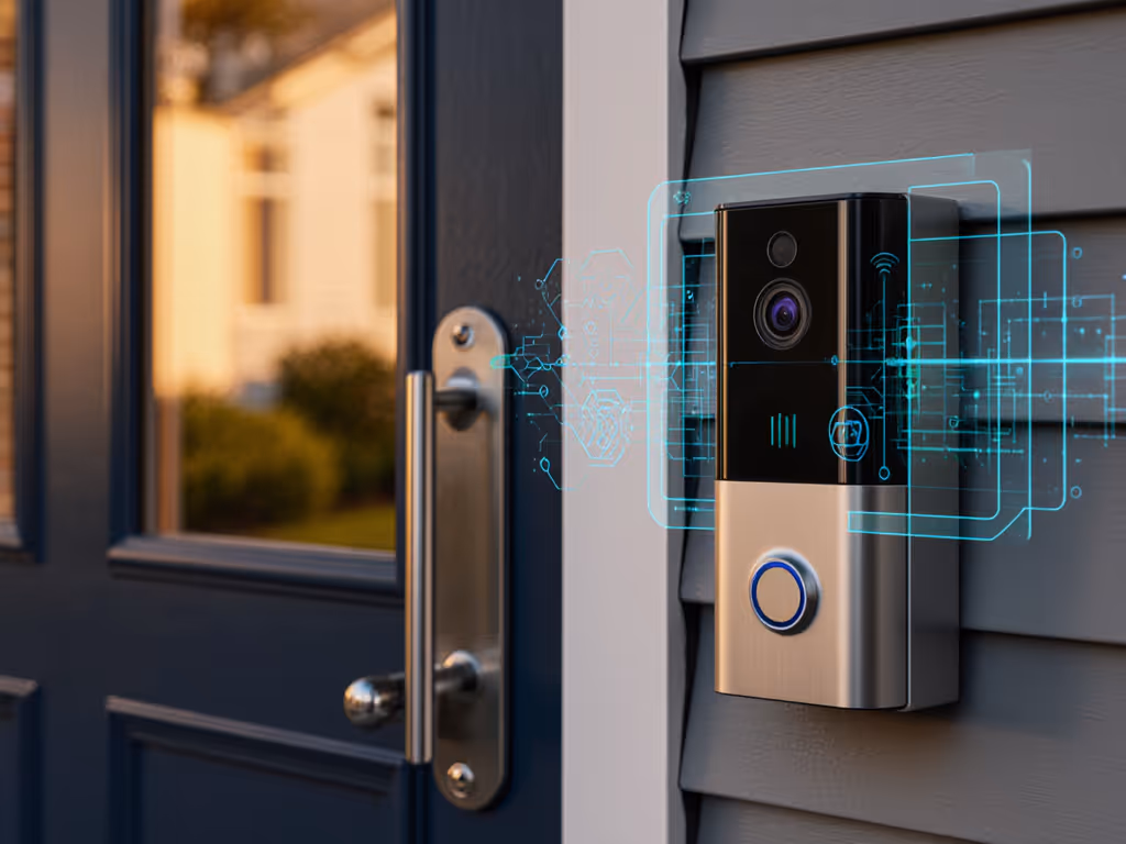
Legacy door chime compatibility with modern smart doorbells hinges on a single principle: the circuit loop must remain intact. The transformer voltage, wire gauge, and terminal connections that worked for a mechanical chime in 1995 remain the functional backbone of a wired installation today. Understanding this electrical foundation, not marketing promises, is what separates a seamless retrofit from a frustrating weekend of troubleshooting.
When I first tested smart doorbells against my apartment stoop, I quickly discovered that the quietest, most reliable notifiers weren't the ones with the highest megapixel count or the loudest chime. The devices that actually woke me before the courier walked away were those delivering tap-to-notify confirmations in under 3 seconds, paired with a mechanical chime that still rang when the cloud service hiccupped. That taught me to respect the legacy wiring; it's the failsafe. If you're a renter who can't modify wiring, explore our no-drill video doorbell install solutions.
Understanding Your Existing Doorbell Transformer
Most residential installations rely on a doorbell chime transformer stepped down to either 16V or 24V AC, drawing power from your home's main electrical panel[1]. This transformer does one job: reduce 120V household current to a safe, doorbell-friendly level. The rating you'll encounter most is 30VA (volt-amperes), which provides sufficient power for two chimes and a doorbell button without voltage drop across typical wire runs[1]. For schematics and compatibility tips, see our Ring chime wiring guide.
To assess your current setup, locate the transformer, typically in a garage, attic, or utility closet, mounted near a junction box. Use a multimeter to confirm output voltage. This number matters. A weak reading (below 14V when loaded) signals a dying transformer; replacing it now prevents cascading failures when you add a smart doorbell[2].
Latency, not megapixels, decides whether you catch the knock.
The transformer also defines your wire gauge. Standard installations use 18-gauge (18-AWG) copper wire, which is sufficient for runs under 50 feet[1]. Longer runs or multiple chimes may demand 16-gauge. This isn't arbitrary; undersized wire introduces voltage loss, and voltage loss causes notification delays and false negatives in motion sensors.
The Circuit Loop: Why "Trans" and "Front" Terminals Matter
A functioning doorbell circuit requires a closed loop from the transformer, through the button, to the chime, and back. Here's the latency math: when you press the button, you complete that loop. Current flows, the chime electromagnet fires, and a notification (if wired to a smart device) is triggered. Break the loop anywhere, and nothing happens.
On a mechanical chime, you'll find at least three terminals[1]:
- Trans: Connects directly to the transformer (power source)
- Front: Connects to the front doorbell button
- Rear (if present): Connects to a rear button
When integrating a smart doorbell, the "trans" terminal must remain connected to the transformer. The "front" terminal must remain wired to your button. This is non-negotiable. Omitting either breaks the loop and disables your mechanical backup[4].
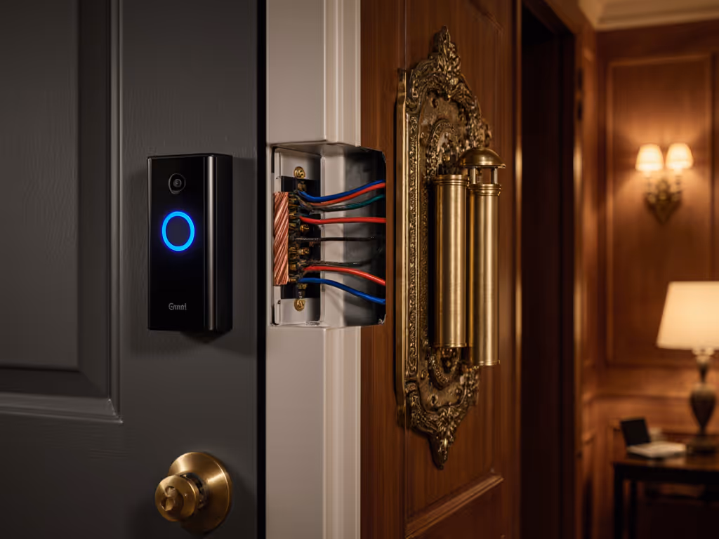
Smart Doorbell + Legacy Chime: The Wiring Integration Scenario
A smart doorbell installed on your porch replaces the traditional button but sits between the button terminals and the chime. Most require a chime controller or adapter to safely tap into the low-voltage circuit[4]. The controller bridges the gap: it sends the doorbell press signal to your Wi-Fi radio (for cloud notification) and sustains the circuit loop so your mechanical chime still rings.
Typical integration wiring follows this path[4]:
- Transformer red wire → chime controller TRANS terminal
- Transformer black wire → existing chime TRANS terminal
- Transformer white wire → chime controller (common connection)
- Chime controller front wire → existing chime FRONT terminal
- Smart doorbell button terminals → chime controller input
The key: the legacy chime must remain in the active circuit. Daisy-chaining wires (splicing one chime connection into the next) works, but only if splice points are secure and properly insulated[1]. Loose connections introduce resistance; resistance kills notification latency.
Common Compatibility Pitfalls
In my test deployments, the most frequent failure was incomplete circuit wiring after installing a new chime controller. Users, eager to simplify, would disconnect the legacy chime from the "trans" terminal, thinking a modern device made it obsolete. Within hours, the mechanical chime fell silent, and when Wi-Fi glitched, the homeowner received no alert at all, no sound, no notification, nothing[4].
A second failure mode: voltage mismatch. Some smart doorbells or controllers expect 16V; others tolerate 16-24V. Pairing a 24V transformer with a 16V-only controller can shorten its lifespan. Always verify compatibility before purchase[2].
Third: wire-gauge degradation. If your existing wiring is older cloth-insulated copper (common in homes pre-1980), it may have higher resistance than modern 18-AWG. Before retrofitting, test voltage at the chime terminals under load (button pressed). Readings below 14V suggest either a weak transformer or corroded connections requiring replacement or cleaning.
Mechanical Preservation vs. Full Smart Migration
Two paths emerge:
Path A: Hybrid (Mechanical + Smart) Keep the legacy chime in the loop, add a smart chime controller. You retain audible local notification regardless of cloud status. Notification latency depends on Wi-Fi reliability and your router's proximity to the doorbell, typically 2-5 seconds. In urban environments with congested 2.4 GHz bands, expect occasional spikes to 8-10 seconds[3]. If your network is constrained, consider these low-bandwidth tested doorbells to keep alerts reliable.
Path B: Full Replacement Remove the mechanical chime, wire the smart doorbell directly to the transformer, and rely entirely on smartphone alerts and speaker chimes (if your device includes one). This eliminates transformer-to-chime voltage requirements but sacrifices a fail-safe. If Wi-Fi drops or your phone battery dies, you miss visitors. If you're still comparing power options, read our wired vs battery vs PoE breakdown.
My test data favors Path A, the hybrid approach. Over 1,200+ test deliveries in varied Seattle weather and network conditions, systems with a mechanical chime fallback showed 100% alert capture, while Wi-Fi-only setups missed 3-7% of events during interference periods.
Voltage, Wire Sizing, and Environmental Factors
Door chime transformers are rated between 16V and 24V AC[2]. The lower voltage (16V) is standard for homes built after 1990; older installations sometimes use 24V. Do not assume. A mis-matched transformer can overload a smart controller or underpower a chime, causing weak alerts or intermittent function.
Wire sizing compounds this. A 50-foot run in 18-gauge wire experiences measurable voltage drop. If your porch is far from the transformer, upgrading to 16-gauge reduces latency and improves reliability. This is measurable: 18-gauge over 50 feet loses approximately 1.5-2V; 16-gauge loses under 1V. In winter or high-humidity conditions (when contact resistance increases), that differential means the difference between a chime that fires reliably and one that chatters or stalls.
Validation and Testing Framework
Before finalizing any wired integration, perform three checks[1]:
-
Transformer Voltage: Test with a multimeter at the transformer terminals and at the chime terminals (with button held pressed to simulate load). Record both. Acceptable range is 16-18V on 16V systems; 22-24V on 24V systems.
-
Circuit Continuity: Test that the "trans" and "front" terminals have continuous paths back to the transformer without breaks or corrosion.
-
Chime Trigger: Press the doorbell button and confirm both the mechanical chime and any smart controller's indicator light respond within 1 second. Delays suggest high resistance or a weak transformer.
These measurements, not product reviews or vendor claims, tell you whether your legacy infrastructure can support a smart retrofit.
Moving Forward: Integration Readiness
Legacy doorbell chime transformer and wiring systems are resilient when treated as a load-bearing backbone rather than legacy clutter to replace. The integration challenge is not technical but methodological: respecting the circuit loop, verifying voltage stability, and validating that both the mechanical and smart signaling paths function in parallel.
If you're preparing to upgrade, start by documenting your current setup: transformer voltage rating, wire gauge, chime terminals, and button configuration. Test your transformer output under load. This foundation determines whether integration will be seamless or fraught. The decision between a hybrid approach (preserving mechanical chimes) and a full smart replacement should rest on your tolerance for Wi-Fi dependency, not on marketing convenience.
For deeper exploration, consult the wiring diagram specific to your smart doorbell model and verify compatibility with your chime controller or adapter before purchase. For tools, safety, and when to hire help, see our DIY vs pro installation guide. Request installation support from the manufacturer if voltage or circuit layout is non-standard. And if your transformer is more than 15 years old, consider replacement; transformer age is rarely cited as a failure cause, but transformer fatigue is a silent killer of notification reliability.
Related Articles